INDOOR POWER SUPPLY
SCOPE OF INDOOR POWER SUPPLY DESIGN

The indoor power supply project is an integral part of the project of any building and structure. The project is being carried out for both newly constructed facilities and facilities in which reconstruction is envisaged.
A professionally executed project is always carried out in accordance with applicable rules and regulations, based on the architectural features of a building or structure, related engineering requirements, while taking into account the wishes of the customer.

- residential complexes,
- shopping centers,
- hospitals and clinics,
- restaurants and cafes,
- educational institutions,
- office premises,
- car dealerships and trade and exhibition centers,
- hotels,
- sports and recreation complexes
- oil extraction plants,
- food processing plants,
- enterprises for storage and handling of grain,
- enterprises of the paint and varnish industry, etc.
Residential complexes
Medical centers
Restaurants

DESIGN STAGES
- Explanatory note;
- Calculation of loads, short-circuit currents, voltage losses in lines, etc .;
- Schematic diagrams of the power supply network;
- Distribution network schematic diagrams;
- Control schematic diagrams;
- Electrical equipment layout plan;
- Plans for lighting and distribution networks, grounding networks;
- Cable list;
- Biil of materials and equipment
- Estimated documentation of the cost of electrical equipment and electrical installation work.
Technical specification (requirements)
The most important document in the design is the technical requirements. There is a document that provides comprehensive information on how exactly the project documentation should be executed. The Terms of Reference is drawn up in close cooperation between the Contractor and the Customer and must be performed in such a way that:
- The customer received exactly the product he wanted to receive;
- The customer spent a minimum and sufficient amount of financial resources on the construction;
- The contractor completed the work for the minimum and sufficient time for this.
- Electrical indicators of the design object;
- Brief description of the design object;
- Calculation of electrical loads;
- Calculation of reactive power compensation devices;
- Principles of reception and distribution of electricity applied in the project;
- Electricity metering solutions;
- Basic solutions for the laying of all electrical networks;
- Protective measures;
- Energy saving and environmental protection solutions.
Electrical diagrams
Single-line wiring diagrams provide the most disclosed idea of how the equipment used on the site works.
The schematic diagrams display all functional units of the electrical circuit, connections between them, data on the wiring used, etc. They serve as the basis for the development of other project documents: cable logs, electrical panels and consoles, external connection diagrams, etc.


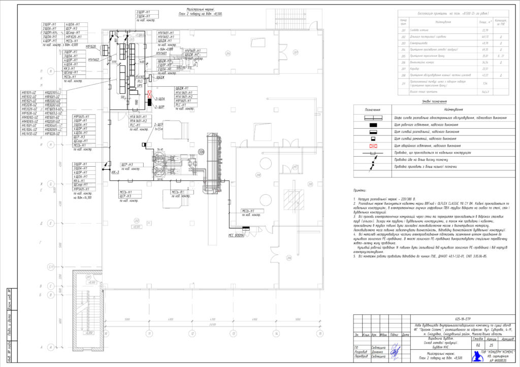
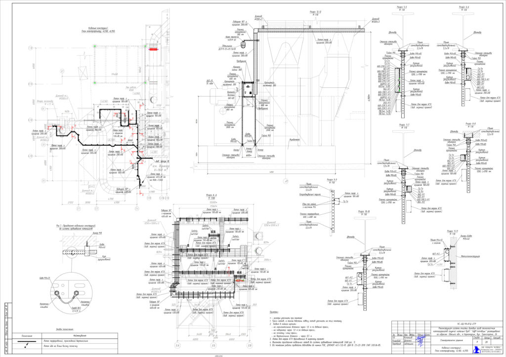
On the plans for laying cable routes, the location of networks and electrical equipment, electrical panels, consoles, electrical appliances, etc. is displayed. The plans are drawings and sections of the premises with an indication of the ways of laying the methods to a specific electrical consumer at each specific site.
Cable routing is usually carried out in trays or in ducts laid on cable structures. A feature of laying on cable trays is protection against mechanical damage, good placement, ease of installation, accessibility for cable inspection, good appearance.
The use of cable structures, trays, boxes of appropriate designs allows them to be used in difficult operating conditions.
For each section in the drawing, a section is made with the arrangement of cables in trays in order to minimize the intersections of the wiring and for quick orientation along the laying of electrical networks.
